XD-204 Shield Data Logger Compatible con Arduino UNO
$ 81.00
51 disponibles
| CANTIDAD | PRECIO |
|---|---|
| 10 piezas | $ 70.45 |
| 25 piezas | $ 62.89 |
| 35 piezas | $ 56.80 |
INFORMACIÓN
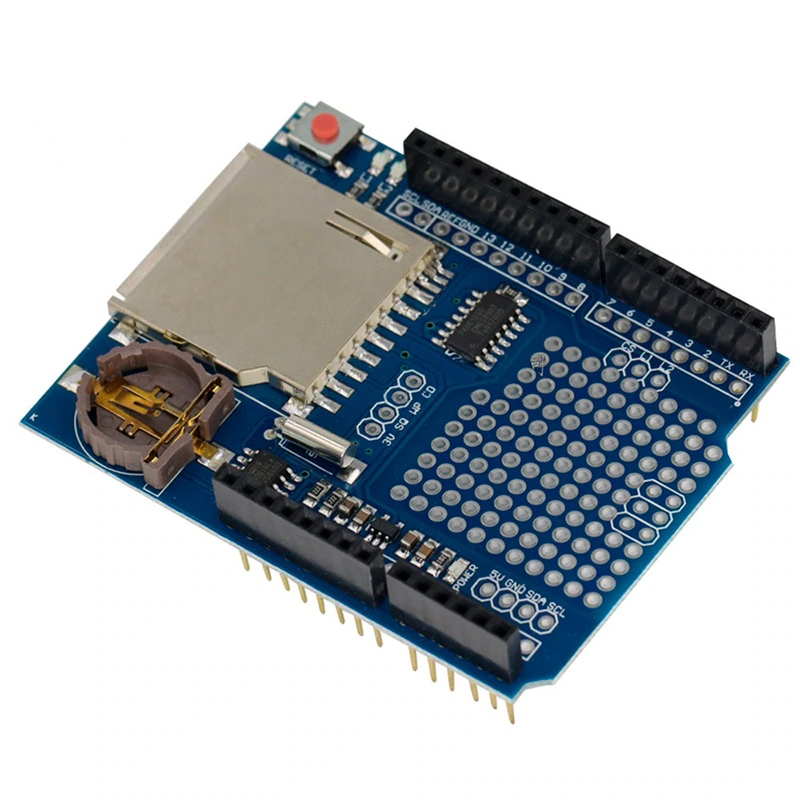
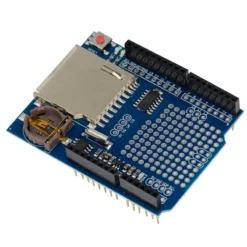
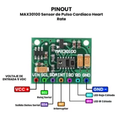
El XD-204 Shield Data Logger compatible con Arduino UNO es una placa de expansión diseñada para facilitar el registro de datos de sensores en una tarjeta SD, también ofrecer un reloj de tiempo real (RTC) para llevar control de fecha y hora. Se instala directamente sobre el Arduino mediante el sistema de pines tipo shield, permitiendo que el microcontrolador lea sensores, genere datos y los guarde ordenadamente en archivos de texto en la SD. Su funcionamiento se basa en un módulo lector de tarjetas SD que usa comunicación SPI, y un chip RTC que se comunica por I2C.
El XD-204 Shield Data Logger se utiliza principalmente para proyectos donde es necesario almacenar información de manera continua, como medición ambiental, monitoreo de sensores industriales, registro de voltajes, sistemas de seguridad, estaciones meteorológicas, seguimiento de variables en proyectos escolares y cualquier aplicación que requiera guardar datos sin depender de una computadora. Gracias a su diseño tipo shield, es totalmente compatible con Arduino UNO, y también puede usarse con otras tarjetas basadas en el mismo formato de pines como Arduino Mega 2560, Arduino Leonardo.
ESPECIFICACIONES Y CARACTERÍSTICAS
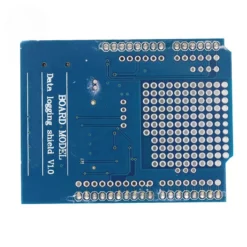
- Modelo: XD-204 Shield Data Logger.
- Compatible con:
- Arduino UNO.
- Mega 2560.
- Leonardo.
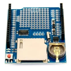
- Lector de tarjetas microSD para almacenamiento de datos.
- Soporta Formatos: FAT16 y FAT32 (Flashear antes de usar la SD).
- Comunicación:
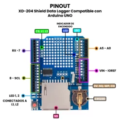
- Comunicación con la tarjeta SD mediante SPI (pines 10, 11, 12, 13 en Arduino UNO).
- Comunicación del RTC mediante I2C (pines A4 – SDA y A5 – SCL en Arduino UNO).
- Incorpora Reloj de Tiempo Real (RTC).
- Batería de respaldo tipo CR1220 para mantener fecha y hora aun sin energía (NO INCLUIDA).
- Regulador de 3.3 V integrado para alimentar la tarjeta SD de forma segura.
- Conversión de nivel de voltaje para trabajar con Arduino de 5 V.
- Área de prototipado para agregar sensores y circuitos personalizados.
- LEDs Indicadores:
- Power.
- D1.
- D2.
- Dimensiones: 68 mm x 53 mm x 23 mm.
- Peso: 16 g.
DOCUMENTACIÓN Y RECURSOS
INFORMACIÓN ADICIONAL
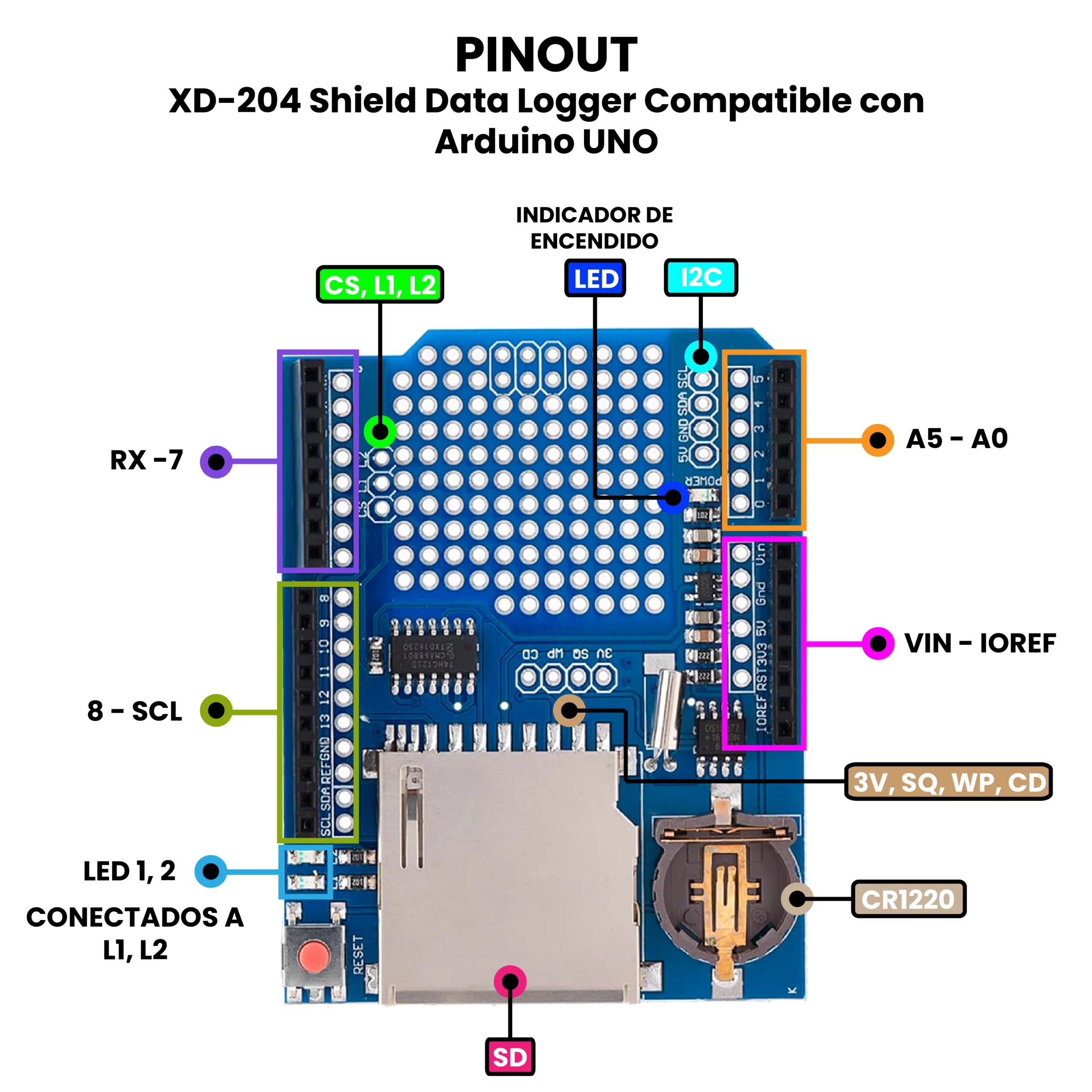
Descripción de Pines Soldables.
- CD: Este es el pin de detección de la tarjeta SD. Cuando se conecta a tierra, se inserta una tarjeta SD. Es de drenaje abierto; utiliza una resistencia pull-up (ya sea física o habilitada por software).
- WP: Este es el pin de protección contra escritura de la tarjeta SD. Puedes usarlo para detectar si la tarjeta tiene la pestaña de protección contra escritura revisando este pin. Es de drenaje abierto; usa una resistencia pull-up (ya sea física o habilitada por software).
- SQ: Esta es la salida de onda cuadrada opcional del RTC. Debe enviar el comando para activarla, pero es una forma de obtener opcionalmente una onda cuadrada de precisión. La usamos principalmente para pruebas. La salida es de drenaje abierto, por lo que es una resistencia pullup (ya sea física o habilitada por software).
- 3 V: Esta es la salida de 3 V del regulador. Es una referencia de 3,3 V de buena calidad que podría ser útil para alimentar sensores. Disponible hasta 50 mA.
- CS: Este es el pin de selección de chip de la tarjeta SD. Si necesita cortar la pista al pin 10 porque está en conflicto, puede soldar esta pista a cualquier pin digital y volver a cargar el software, de forma predeterminada se encuentra en el PIN 10.
- L2 y L1: Son LED de usuario opcionales. Se conectan a cualquier pin digital y se activan en alto para encender el LED correspondiente (D1, D2). Los LED ya tienen resistencias de 470 ohmios en serie.
¿Cómo probar XD-204 Shield Data Logger Compatible con Arduino UNO?
Te presento una guía rápida para probar el shield como lector de memorias SD, y como RTC.
Lector de Memorias SD.
Debes cargar el siguiente código en tu Arduino UNO:
/*
  SD card test

  This example shows how use the utility libraries on which the
  SD library is based in order to get info about your SD card.
  Very useful for testing a card when you're not sure whether its working or not.
  Pin numbers reflect the default SPI pins for Uno and Nano models.
  The circuit:
    SD card attached to SPI bus as follows:
 ** SDO - pin 11 on Arduino Uno/Duemilanove/Diecimila
 ** SDI - pin 12 on Arduino Uno/Duemilanove/Diecimila
 ** CLK - pin 13 on Arduino Uno/Duemilanove/Diecimila
 ** CS - depends on your SD card shield or module.
 		Pin 10 used here for consistency with other Arduino examples

  created  28 Mar 2011
  by Limor Fried
  modified 24 July 2020
  by Tom Igoe
*/
// include the SD library:
#include <SPI.h>
#include <SD.h>

// set up variables using the SD utility library functions:
Sd2Card card;
SdVolume volume;
SdFile root;

// change this to match your SD shield or module;
// Default SPI on Uno and Nano: pin 10
// Arduino Ethernet shield: pin 4
// Adafruit SD shields and modules: pin 10
// Sparkfun SD shield: pin 8
// MKR Zero SD: SDCARD_SS_PIN
const int chipSelect = 10;

void setup() {
  // Open serial communications and wait for port to open:
  Serial.begin(9600);
  while (!Serial) {
    ; // wait for serial port to connect. Needed for native USB port only
  }


  Serial.print("nInitializing SD card...");

  // we'll use the initialization code from the utility libraries
  // since we're just testing if the card is working!
  if (!card.init(SPI_HALF_SPEED, chipSelect)) {
    Serial.println("initialization failed. Things to check:");
    Serial.println("* is a card inserted?");
    Serial.println("* is your wiring correct?");
    Serial.println("* did you change the chipSelect pin to match your shield or module?");
    Serial.println("Note: press reset button on the board and reopen this Serial Monitor after fixing your issue!");
    while (1);
  } else {
    Serial.println("Wiring is correct and a card is present.");
  }

  // print the type of card
  Serial.println();
  Serial.print("Card type:         ");
  switch (card.type()) {
    case SD_CARD_TYPE_SD1:
      Serial.println("SD1");
      break;
    case SD_CARD_TYPE_SD2:
      Serial.println("SD2");
      break;
    case SD_CARD_TYPE_SDHC:
      Serial.println("SDHC");
      break;
    default:
      Serial.println("Unknown");
  }

  // Now we will try to open the 'volume'/'partition' - it should be FAT16 or FAT32
  if (!volume.init(card)) {
    Serial.println("Could not find FAT16/FAT32 partition.nMake sure you've formatted the card");
    while (1);
  }

  Serial.print("Clusters:          ");
  Serial.println(volume.clusterCount());
  Serial.print("Blocks x Cluster:  ");
  Serial.println(volume.blocksPerCluster());

  Serial.print("Total Blocks:      ");
  Serial.println(volume.blocksPerCluster() * volume.clusterCount());
  Serial.println();

  // print the type and size of the first FAT-type volume
  uint32_t volumesize;
  Serial.print("Volume type is:    FAT");
  Serial.println(volume.fatType(), DEC);

  volumesize = volume.blocksPerCluster();    // clusters are collections of blocks
  volumesize *= volume.clusterCount();       // we'll have a lot of clusters
  volumesize /= 2;                           // SD card blocks are always 512 bytes (2 blocks are 1 KB)
  Serial.print("Volume size (KB):  ");
  Serial.println(volumesize);
  Serial.print("Volume size (MB):  ");
  volumesize /= 1024;
  Serial.println(volumesize);
  Serial.print("Volume size (GB):  ");
  Serial.println((float)volumesize / 1024.0);

  Serial.println("nFiles found on the card (name, date and size in bytes): ");
  root.openRoot(volume);

  // list all files in the card with date and size
  root.ls(LS_R | LS_DATE | LS_SIZE);
  root.close();
}

void loop(void) {
}
Este sketch leerá tu tarjeta SD dándote la información de esta como:
- Volumen.
- Clusters.
- FAT.
- Espacio Ocupado.
- Espacio Disponible.
Este código también lo puedes encontrar desde los ejemplos de Arduino IDE en la sección de la librería SD > CardInfo, recuerda que antes de insertar tu memoria SD, se debe formatear en FAT16 o FAT32, de caso contrario no funcionará correctamente, también considera colocar bien los pines, y que hagan un buen contacto, ya que una falsa conexión, provocará que no se pueda leer, dando errores.
RTC.
Para comprobar el funcionamiento del shield como RTC, primero se debe colocar la batería CR1220 (NO INCLUIDA), después se debe de cargar la librería, para ello desde el Arduino IDE, se abrirá “Library Manager” y ahí buscaremos RTClib by Adafruit, una vez que se haya instalado, podremos cargar un ejemplo llamado “DS1307”, si no lo encuentras, aquí lo dejo a continuación:
// Date and time functions using a DS1307 RTC connected via I2C and Wire lib
#include "RTClib.h"

RTC_DS1307 rtc;

char daysOfTheWeek[7][12] = {"Sunday", "Monday", "Tuesday", "Wednesday", "Thursday", "Friday", "Saturday"};

void setup () {
  Serial.begin(57600);

#ifndef ESP8266
  while (!Serial); // wait for serial port to connect. Needed for native USB
#endif

  if (! rtc.begin()) {
    Serial.println("Couldn't find RTC");
    Serial.flush();
    while (1) delay(10);
  }

  if (! rtc.isrunning()) {
    Serial.println("RTC is NOT running, let's set the time!");
    // When time needs to be set on a new device, or after a power loss, the
    // following line sets the RTC to the date & time this sketch was compiled
    rtc.adjust(DateTime(F(__DATE__), F(__TIME__)));
    // This line sets the RTC with an explicit date & time, for example to set
    // January 21, 2014 at 3am you would call:
    // rtc.adjust(DateTime(2014, 1, 21, 3, 0, 0));
  }

  // When time needs to be re-set on a previously configured device, the
  // following line sets the RTC to the date & time this sketch was compiled
  // rtc.adjust(DateTime(F(__DATE__), F(__TIME__)));
  // This line sets the RTC with an explicit date & time, for example to set
  // January 21, 2014 at 3am you would call:
  // rtc.adjust(DateTime(2014, 1, 21, 3, 0, 0));
}

void loop () {
    DateTime now = rtc.now();

    Serial.print(now.year(), DEC);
    Serial.print('/');
    Serial.print(now.month(), DEC);
    Serial.print('/');
    Serial.print(now.day(), DEC);
    Serial.print(" (");
    Serial.print(daysOfTheWeek[now.dayOfTheWeek()]);
    Serial.print(") ");
    Serial.print(now.hour(), DEC);
    Serial.print(':');
    Serial.print(now.minute(), DEC);
    Serial.print(':');
    Serial.print(now.second(), DEC);
    Serial.println();

    Serial.print(" since midnight 1/1/1970 = ");
    Serial.print(now.unixtime());
    Serial.print("s = ");
    Serial.print(now.unixtime() / 86400L);
    Serial.println("d");

    // calculate a date which is 7 days, 12 hours, 30 minutes, and 6 seconds into the future
    DateTime future (now + TimeSpan(7,12,30,6));

    Serial.print(" now + 7d + 12h + 30m + 6s: ");
    Serial.print(future.year(), DEC);
    Serial.print('/');
    Serial.print(future.month(), DEC);
    Serial.print('/');
    Serial.print(future.day(), DEC);
    Serial.print(' ');
    Serial.print(future.hour(), DEC);
    Serial.print(':');
    Serial.print(future.minute(), DEC);
    Serial.print(':');
    Serial.print(future.second(), DEC);
    Serial.println();

    Serial.println();
    delay(3000);
}
Sigue las instrucciones del void setup, para configurarlo o darle un reset, una vez que lo tengos subido en tu Arduino UNO, aparecerá en el Serial Monitor, la hora exacta junto con el día actual. Si lo configuraste bien podrás desconectar la energía, y aunque pase el tiempo, el RTC mantendrá en todo momento la hora y el día, gracias a la pila CR1220.
ENLACES EXTERNOS
- Tutorial: How to Use Arduino Data Logger Shield – MyBotic
- How To Calibrate the RTC For Data Logger Shield – Coding with Alfred
| Peso | 0.019 kg |
|---|---|
| Dimensiones | 10 × 4 × 14.5 cm |
| TIPO DE SHIELD: | EXPANSIÓN, MULTIFUNCIÓN |
| FORMATO: | UNO |
Solo los usuarios registrados que hayan comprado este producto pueden hacer una valoración.
También te recomendamos…

Productos relacionados
COMPATIBLES CON ARDUINO
Valoraciones
No hay valoraciones aún.